PhoneWave (name subject to change) HowTo: build remote control function & send D-Mails
This microwave modification has been designed to recreate the remote control function of the PhoneWave (used in Steins;Gate) including a mod to use it in the process of sending D-Mails. I tried to make it as cheap and easy as possible, so it won’t be 100% like the original PhoneWave. In this process, all heating devices will be removed from the microwave. Also, this is a modified version (fixed bugs and added Raspberry Pi) of my attempt to create it. The layouts and instructions here refer to the modified version. The “legacy” layouts (to be found in the layouts repository) were my foundation, upon which i added the Raspberry Pi later on to extend the microwave’s functions. I can’t guarantee 100% success, since i haven’t build the board using the new layout i designed just for you.
needed skills:
- basic linux terminal commands
- installing programs from source code
- some electronic engineering knowledge
- soldering skills
- hopefully having worked with stripboards before
needed hardware:
- a microwave with 7-segments LED displays
- MyAvr board light
(may be done with an Arduino or different board based on ATmega8 too, but code may need to be rewritten then!) - Raspberry Pi with Raspbian as operating system (tested with Pi model 3B)
- 160mm x 100mm stripboard (like this one)
- 75mm x 100mm stripboard (like the one above, but smaller)
- 8x 100 Ω Resistors
- 1x 100 kΩ Resistor
- 7x 2.8 kΩ Resistors
- 1x 230 Ω Resistor
- 12x MPSA42 TO-92 1 NPN transistors
- PE014005 Relay
- X2 Capacitor
- 1N4007 Diode
- bidirectional logic level converters (3.3v to 5v and the other way round too) (you need to connect 5 pins of the ATmega8 to the Raspberry Pi with them. choose your favourite converter)
- connectors (jumper cables or other means of connecting, you need to evaluate it yourself, depending on how you want to build and connect your circuits)
- many copper wires
- soldering equipment
if you want to make the setup portable to a certain degree: - Powerbank
- Huawei USB dongle which is compatible with chan_dongle and has voice capabilities (list of compatible models) (I use the HUAWEI K3520)
- Your own server (virtual or physical) to run an email-server on
needed software:
- USB-Driver for myAVR-products
- myAVR ProgTool Version 1.41
- Atmel Studio (if you want to adust the source code for your microcontroller or need to recompile it for another ATmega chip)
- Code for Atmel ATmega8 and Layouts for the extension boards: download
- latest Raspbian for your Raspberry Pi
- SIP-Pi software: download
- LochMaster 4 & KiCAD (if you want to edit the circuit & extension board layout files)
For making it portable: - Asterisk: download
- chan_dongle: download
For sending D-Mails: - Postfix & Dovecot Email Server – Google a nice tutorial for that please.
- dmail-connect: download
- dmail-datechanger: download
How is it working, who does what?
| ATmega8 & self-built extension boards | Raspberry Pi’s SIP-Pi sipserv | Asterisk & chan_dongle |
| Receives numeric DTMF signal on Ports C0-3
converts them into regular numbers |
connects to SIP/VoIP provider acts as an answering machine that acts on pressed numbers Forwards the pressed numbers as numeric DTMF signal to ATmega8 via Pi’s GPIO. Sends the numbers on display to dmail-connect |
Asterisk: your own local SIP/VoIP serverchan_dongle: a bridge between the GSM network and your asterisk serverWhen used together, Asterisk can access GSM network (incoming & outgoing calls) |
| Postfix&Dovecot (the email server) | dmail-connect (on E-Mail server) |
| Dovecot: sends email to client (via POP3 or IMAP)Postfix: receives e-mails from clients and servers gives them to the dmail-datechanger filter sends them to destination e-mail address |
Receives and saves numbers (time offset for D-Mail) from sipserv (which runs on your Raspberry Pi in the microwave) via internet Relays those to dmail-datechanger when requesteddmail-datechanger: Requests the time offset from dmail-connect. then edits the email and replaces timestamps with a timestamp that is x hours older. |
How the finished project looked like in my case:
-
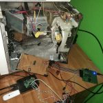
- legacy layout used with Raspberry Pi & Huawei upgrade (from the side)
-
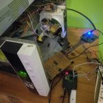
- legacy layout used with Raspberry Pi & Huawei upgrade
Preparing the microwave:
First, everything is thrown out of the microwave except of the LED Displays and the power module (should be small) as well as the turntable motor and the lights. Depending on the microwave it may be worth keeping the mainboard, where the display is mounted on, just to use it as a socket to keep the display in the right place. But the Mainboard has to be electrically disconnected from the display. If the mainboard is being kept, it has to be disconnected from any electricity. We will never play with microwave radiation since it is too dangerous for us. Then, everything (especially the microwave radiator and the capacitor) except of the mentioned parts are being removed. Be careful with the massive capacitor, which looks like a giant battery. It has a lot of capacity, and if you short circuit it, you will harm yourself!
Now you need to check out the display you have. I have a 4×7 segment display with one common anode for each 7-Segment display.
Notice: The example display’s 4 7-segment-displays (example display: JLDF-4431BHGBD20 930, uses green LED’s) share their segment connectors. Technically, only one 7-segment-display and it’s segments can be turned on at the same time, and be switched off again after. The program on the ATmega8 switches between the 4 displays so quickly that your brain won’t notice that any of them have been turned off at all. That’s some type of multiplexing the manufacturer of the display used to reduce the number of ports needed. For each display, the connectors may be at different places. Before continuing to build this gadget, the type of display your microwave uses and the position of the needed connectors on said display have to be figured out. Depending on the display, the layout of the circuit and possibly the software on the ATmega8 have to be adjusted. Depending on the used LED’s in the display, the resistors for the LED segments have to be swapped with others matching the resistance the LED’s need. If your display is designed similar to mine, nothing has to be changed.
Building the circuits:
The files extensionBoard_withPiConn.jpg and extensionBoard_withPiConn_back.jpg provide the layout for the 160mm x 100mm stripboard. Simply aim to replicate that layout on your stripboard. One side of the stripboard has a copper coating. This coating needs to be disrupted at certain places marked with the yellow spaces.
relay microwave.jpg and relay microwave back.jpg provide the layout for the high-voltage controlling parts of our circuit (230v motor and lamp)
The back pictures describe how it should look like when you turn it over to see the copper coating.
The circuits are documented in Board_withPiConn.sch (KiCAD file for schematic drawing of the circuits) and myAvr Atmega8 extension SteinsGate PhoneWave_noMT8870.LM4 as well as relay microwave.LM4 (LochMaster 4 Files, Layout of the actual board)
Turn the board, so that the plastic side is facing up. Stick all your components and copper wires into their respective holes. Get some masking tape and tape the components, so they won’t fall off when you turn your board upside down. Then, turn it upside down (copper side facing up) and solder the ends of the components onto the copper coating. Make sure, that the components do not have any electrical contact to neighbouring copper lanes. After that is finished, cut off the ends of the components that stick out. When that is finished, make all disruptions in the copper coated lanes according to the plan. Remove the masking tape and do the same with the smaller stripboard and its layout. Now connect your LED display with the main stripboard. Connect the first 5V output with the 5V input of the very left LED 7-Segment-Display and so forth. After those are full, connect the multiplexed segments of the display to the segment connectors. Use the first connector for segment a, the second for segment b, and so forth. Which segment has which letter can be found in this picture.

segment letters
Then connect the smaller board to the bigger board by connecting the 5V of both boards and connecting the ground voltage of both boards. Then connect the relay control connector to the smaller boards connector for the microcontroller signals.
Now you can connect the 230V power source to the 230V Phase connector and the AC motor and AC lights between the motor in & out connectors. I use the microwave’s power module for 230V.
Depending on your ATmega8 board, you can power the controller and it’s extension boards through its USB connection. Works fine with USB chargers and powerbanks.
Preparing the microcontroller (myAVR board)
For other microcontrollers, this part will be different! In general, if an ATmega8-based board is being used, the code has to be recompiled and uploaded to the board. The instructions below are only valid for the myAVR board specified above.
In case the specified myAVR board above is being used, it has to be assembled first according to the instructions of that board, and then the provided precompiled program may be used. Before programming the board, the myAVR drivers outlined as well as the myAVR ProgTool have to be installed. After having installed the drivers, the myAVR Board has to be connected to the PC.
Then start the ProgTool and set it to English (on the left side). After having restarted the tool then, click the tab Hardware and select your microcontroller at the bottom (ATmega8). Then select myAVR Bootloader and click the ? next to the Connection text box. Then press the reset button on your board. Then go into the Burn Tab and select the file you need to burn into the flash. select the .hex file in the PhoneWave → Debug folder. Make sure, that burning the EEPROM is DISABLED! Then click burn and press reset, and it will program your microcontroller.
Setting up the Raspberry Pi
Install the latest Raspbian on your Raspberry Pi.
Connect the ATmega8’s Ports C0-3 and D2 to the Raspberry Pi using the Logic Level Converters in the middle. Write down to which ports (according to the wiringPi numbering scheme) you connect them.
Then, you need either a SIP provider and phone number or the Huawei USB Dongle. In these instructions, we’re going the easy way using a SIP provider online. SIP provides you with Voice over IP telephony.
After having registered with a sip provider, you need to download and install the sipserv from the SIP-Pi package above to use the Raspberry Pi as Voice over IP answering machine. Follow the instructions to install sipserv with forwarding DTMF to GPIO capabilities. You need to write your own configuration file for your sip provider. Also, you need to set the DTMF encoding to MT8870. Don’t forget to enable the DTMF forwarding in the configuration file 🙂 Also you need leave information in that config file about your DTMF digit output ports on your Raspberry Pi’s GPIO. The DTMF digit output has to be fed into Port C0-3 of the Atmega8. Set dtmf-0 to the port you connected the Atmega’s Port C0 to, dtmf-1 to the Port you connected Port C1 to and so forth until you have done the same for port C3. Set dtmf-interrupt to the port you connected the Atmega’s Port D2 to.
After everything is set up correctly, the SIP-Pi sipserv module can be started.
Extension: Making the PhoneWave portable! (for conventions)
The challenge we are facing here is connecting the sipserv to the mobile GSM network. This can be done with Asterisk and chan_dongle and a Huawei USB GSM dongle which is compatible with chan_dongle. Please note, that if you want to enable the D-Mails too, that the Pi needs a separate internet connection through any means (using the USB GSM for calls and data simultaneously doesn’t work! You would need an additional mobile data modem). Asterisk serves as a VoIP SIP server and has to be installed on the Raspberry Pi in the microwave. chan_dongle is a driver which allows Asterisk to use the HUAWEI USB GSM modem to handle calls to and coming from the GSM phone network. However, the dongle has to have it’s voice function enabled and needs to be unlocked from its provider. DC-Unlocker can help you with that. And the PIN of its SIM card has to be disabled!
First, install Asterisk 14 or 15 on your Raspberry Pi (apt-get install asterisk asterisk-dev)
Then install usb_modeswitch (if not already installed)
Then, download chan_dongle. Open your Terminal and run “git clone https://github.com/wdoekes/asterisk-chan-dongle.git” to download the source code for chan_dongle. Open the newly created asterisk-chan-dongle folder in your terminal and then follow the building instructions on GitHub. After finishing those, run “make install” in that same terminal.
Once that is done, change your asterisk configuration. A sample configuration for the PhoneWave is available here: download. Configuring Asterisk is some kind of rocket science for Asterisk newbies, so just take the sample configuration and use it as instructed on the download page for the quick solution. Don’t forget to edit the configuration of sipserv, setting the sip-server to localhost and changing the sip credentials to the asterisk user credentials. Now sipserv may be started and called. Happy testing!
Note: Only the ATmega8, the extension board for LED display (and the display itself) and the Raspberry Pi can be powered using 5V USB (through power banks). I have not yet found a way to power the original lamps and original turntable motor using batteries since they rely on 230V AC.
Make sure that the ATmega8 gets 5V 1A and the Raspberry Pi at least 5V 2A!
Extension: Sending D-Mails!
To send D-Mails, a separate self-owned email-server with your own domain has to be set up. For the D-Mail-trick, Postfix and Dovecot are used to create an email server. You will have to receive and send D-Mails through this server. There are dozens of HowTo’s for email servers based on Postfix and Dovecot on the internet, so choose your favourite one and complete it before continuing here.
Once installed, install dmail-connect and dmail-datechanger according to the instructions on their website on your email server. After that is done, SIP-Pi’s sipserv has to be reinstalled on your Pi, following the instructions but following step 8 in the instructions online instead of step 7. Set dtmf-value-forward-srv to your email server in your configuration file.
Then, first start dmail-connect on the email server, and then sipserv on your Raspberry Pi. If everything works fine, you should be able to call your microwave and send or receive emails in the past using your email-server with your email client.
Rhys Donald
Hello. I’ve been trying to set up postfix for quite a while. Although I’m not *bad* at the Linux terminal, I have had no luck setting up postfix.
Can you recommend any good tutorials?